Page 6 of 6 FirstFirst ... 456
Results 51 to 59 of 59

Thread: PWM for less heat in your cell

  1. #51
    scratch1676 Guest
    here is a couple more
    This picture show's the mosfet,heatsink,cooling fan in seperate box. Mosfets are behind the heatsink.


    closeup of inside of box. Yellow wires are only for testing it. you would hook one big negative wire to battery and the other to cell negative.


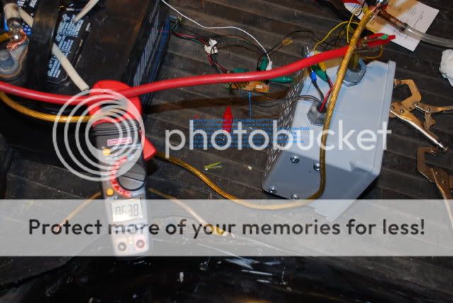
    picture shows mosfet box tested with the circuit board ( hard to see) circuit board will fit under or on dash the mosfet box can be mounted anywhere, closer to cell the better.


    another inside shot of box

  2. #52
    Join Date
    Dec 2008
    Posts
    28

    Resistor set-up

    The resistors (1 ohm & 5 ohm) are bolted together in parallel. This makes a single .83 ohm resistor for the circuit. (R1*R2/R1+R2 or 5/6=.83333)
    This is then wired in series with the cell; in between the cell and the battery...or 40a control relay in my case. I mounted the resistor pack on the fan shroud with the 1 ohm into the air stream for cooling. The 5 ohm doesn't get very warm, most of the current will flow through the 1 ohm. You can see my cell and bubbler tucked down by the radiator and tranny cooling lines. They are a standard pvc case, water bath, brute force style. Very ole' skool. I'm running @ 2.9 vdc at the cell w/ 14 amps. Tied in two Eagle research efie's into the O2 wiring and can turn on/off everything separately. I just finished this one last night, hoping for good results. I'm only running 6 plates, I would like to double that (new plate design needed) for better production year around. I can only stuff so many Lowe's wall plates into a 3" pvc tube. lol
    Hope this helps.
    I also uploaded a pic of one of the poor man's efies I use.

  3. #53
    Join Date
    Dec 2008
    Posts
    28
    test123.........
    Randohr
    02' Jeep; 18mpg Highway w/o HHO
    23mpg highway w/ HHO.
    Parallel plate water baths, 3vdc, 16A
    Efies(x4), MAP diode, AIT mod, WTS mod.

  4. #54
    scratch1676 Guest
    Good work! Hydrogen will get under your skin and you will be wanting more and more production and before you know it 40 amps will seem like it just aint enough. Start making up your next resistor!

  5. #55
    Join Date
    Dec 2008
    Posts
    28
    Yea, I know what you mean. Unfortunately I already smoked two alternators with high current cell tests. My tests indicate,rule-o-thumb, 20 amps is max for the "extra" load above factory design. For safety sake I shoot for 80% of max loading, or 16 amps or less. I want 1000's of square inches of plate area at my max current. Maybe I can turn the entire trunk into a giant parallel HHO cell and the back seat into a bubbler! It would be my monster cell.
    Randohr
    02' Jeep; 18mpg Highway w/o HHO
    23mpg highway w/ HHO.
    Parallel plate water baths, 3vdc, 16A
    Efies(x4), MAP diode, AIT mod, WTS mod.

  6. #56
    I have built 3 PWM's and have had the same results with them all. My understanding is that as your cell draws current, it heats up and this causes it to draw more current which creates more heat and causes it to draw more current..etc.
    I put a strong solution in my cell's and then adjust the current on the PWM to the maximum that I want it to draw and as it warms up, it can't increase the current so that the temperature stabilizes. My single cells are set at 10 amps and with the ambient temperature in the 70's, My cell runs in the 90's.
    I have just completed a dry cell with -NNNNN+NNNNN- and I plan on setting it at 20 amps. As soon as I get it installed, I'll give you some temperature readings from it.
    I'm sure that the amount or volume of your container would make a big difference also.

  7. #57
    Alt-Fuel-Sys Guest
    Quote Originally Posted by Randohr View Post
    This makes a single .83 ohm resistor for the circuit.

    I'm running @ 2.9 vdc at the cell w/ 14 amps.
    Your resistor is burning up 160 watts. Your HHO generator is producing less than 40 watts to put back into the system. That's a loss of more than 120 watts. The energy to do this comes from your fuel tank. I think the PWM is a better choice regulate current.

  8. #58
    Join Date
    Dec 2008
    Posts
    28
    With this system I've documented MPG savings of >40% in my F150 and so far 30%+ in my Z24.
    Total wattage used from the electrical system is about 200 watts. When I experimented with series cells, my wattage was very comparable to this. (14.5vdc * 14 amps) The main difference is I'm "wasting" energy from the alternator at the voltage dropping and current regulating power resistor.
    My goal was to eliminate thermal runaway, lock the current below my rule-o-thumb max of 20 amps, create a system that could be understood by someone without an extensive electrical back ground, be cheap to make, and of course, WORK! I met my goal.
    I know there is more efficient cell designs and better ways to utilize the available wattage. As my 4 years of electronics (US Navy PMEL) and 18+ years as an industrial electrical & instrumentation techy has taught me, sometimes the best solutions are the simplest solutions.

    I do want to try a "series" brute force parallel design. Based on my tests, a cell with proper spacing and saturated electrolyte will exhibit about .3 ohms of usable current limiting resistance. With 4 of these cells in series (12 amps @ 3.6vdc ea), they may lock the current and divide the voltage similarly to what my resistor is doing. But I'd be back to the thermal runaway issue again, but it would take much longer before I blew the fuse. Unless I had a cooling system, and a flow control system and a level system and a current control system and a control panel full of leds and gauges and ...whew... it's no wonder I'm sticking with the resistor, for now. I get enough of the complexity in controls and automation from work.

    On a different note; My Jeep Liberty is showing only about a 2% increase in mpg. My plate spacing is too close to produce enough HHO to make a real difference compared to my other two vehicles (based on O2 readings). I ordered a plate stack from Thegasmaker.com to try. More surface area with increased plate spacing should do the trick. The new plates will be longer and thinner so I can fit more square pegs in my round hole.

    My Z24 cell is using 40.5 watts (4.35mmw) to save me 30%+ on gas. (195.75 watts total from the alternator) I'm happy with this.

    ps. I'm not selling or endorsing anything, just sharing alternatives.

    Take care
    Randohr

  9. #59
    Join Date
    Feb 2012
    Posts
    8

    Red face PMW and HHO

    Quote Originally Posted by thebargew View Post
    From my understanding the pwm is suppose to help you keep the system cool not right off the bat but on long durations. So if you used a high amount of electro to produce a fair amount of hho starting at 10 amps lets say. You would be good for short durations. If you used it for a 4 hour ride your system would be drawing 20+ amps and be much hotter.
    So say your starting at 20amps.... It would be upwards of 30+.

    The idea of more HHO production is not a fast volume but as able to use it longer without changing out your solution.
    My experience using a PMW was that due to the modulation it kept the gas production on a even keel rather then runaway ..what I found was that the smaller particles it creates are more powerful then the bigger ones and one does not need anywhere near as much as some say I was getting 16-17 MPG on my ford International 6.9 and went to 21-22 MPG and it got rid of ALL black smoke from unburned fuel..didn't notice any more power except one time when all of a sudden it took off like nitrous and thank god it was in a straightaway otherwise I would have killed myself!

Posting Permissions

  • You may not post new threads
  • You may not post replies
  • You may not post attachments
  • You may not edit your posts
  •