Senior Member
Senior Member
Senior Member
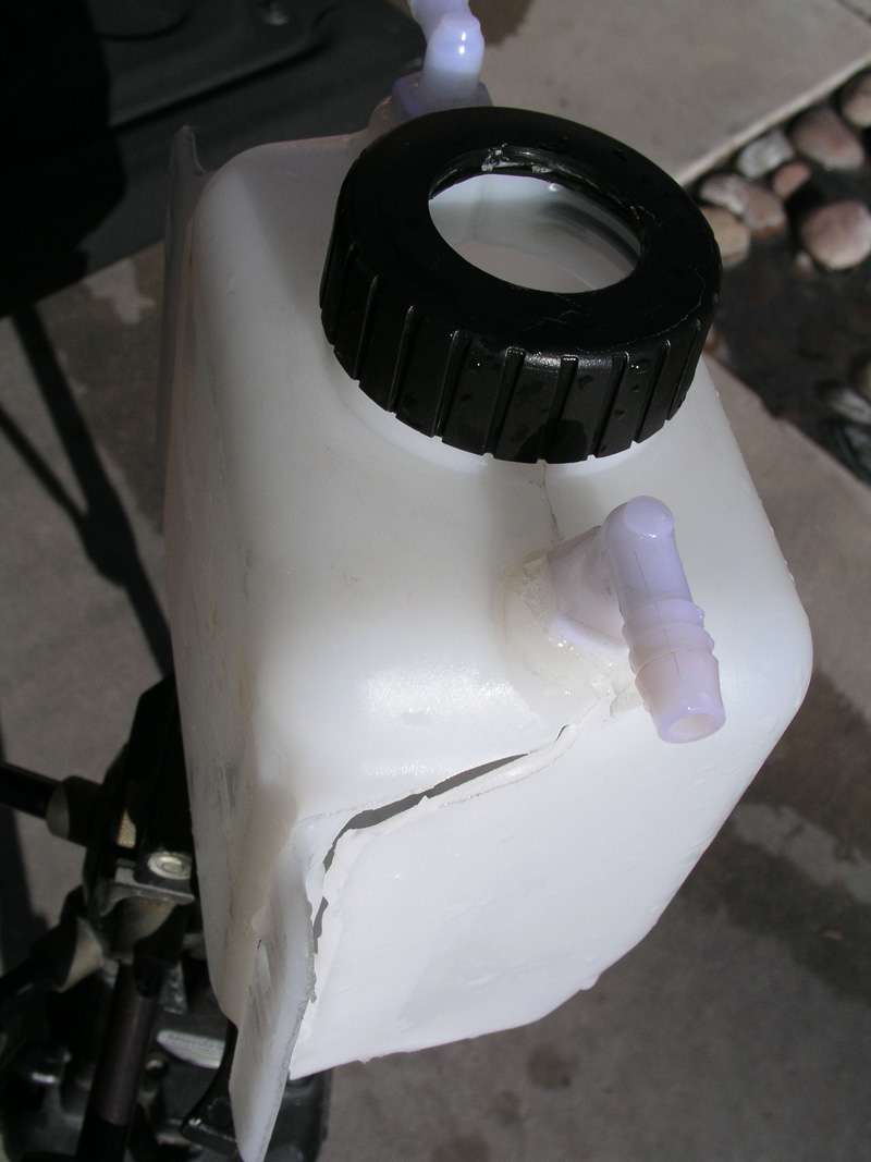
I have begun to construct my flow meter. A friend of mine who own Plastic Plus in Tucson, Arizona has provided me the material to build my flow meter. The base is 6” x 6” and 1” inch thick. The larger tube is 3.5 inches inside measurement and the smaller tube is 1” outside measurement.
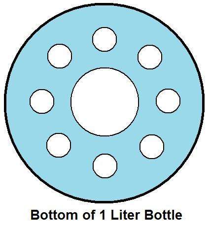
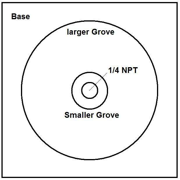
I found a 1 litter plastic water bottle that 3” in diameter and about 12” tall. I have drilled a series of holes in the bottom. The plan is to machine a pair of groves into the 1” block, the larger grove will be 3.75” while the smaller grove will be 1.0”. Next I will drill and tap a ¼” NPT thread directly in the center of the 6” x 6” block. This will support a 90 degree fitting so that I can connect my cell block. Next I will glue the smaller 1” tube to the base followed by the larger tube being glued to the base. Then I will place rubber feet on the bottom of the block to raise the block to clear the 90 degree elbow. I had thought of machining a hole in the side of the block to the center hole and tapping the block to support a fitting, I still may do this if time permits.
Once completed I will fill the larger tube full of distilled water. Removing the cap from the 1 litter bottle I will slide the 1 litter bottle down into the larger tube allowing the 1 litter bottle to completely submerge until the bottle neck comes into contact with the smaller 1” tube. Next I will place the cap back onto the 1 litter bottle tightly. The series of holes I drilled in the bottom of the 1 liter bottle will allow the bottle to rise and at the same time allow the water to exit as HHO gas displaces the water.
Now the flow meter is ready to be used. This will make a very efficient flow meter much better than submerging a bottle in a bucket. The plan is once I see movement is when I will start the stop watch. Once the 1 litter bottle has displaced all water from the bottle is when the stop watch is stopped. The given time on the stop watch will tell me how quickly I produced a litter of HHO gas.
Senior Member
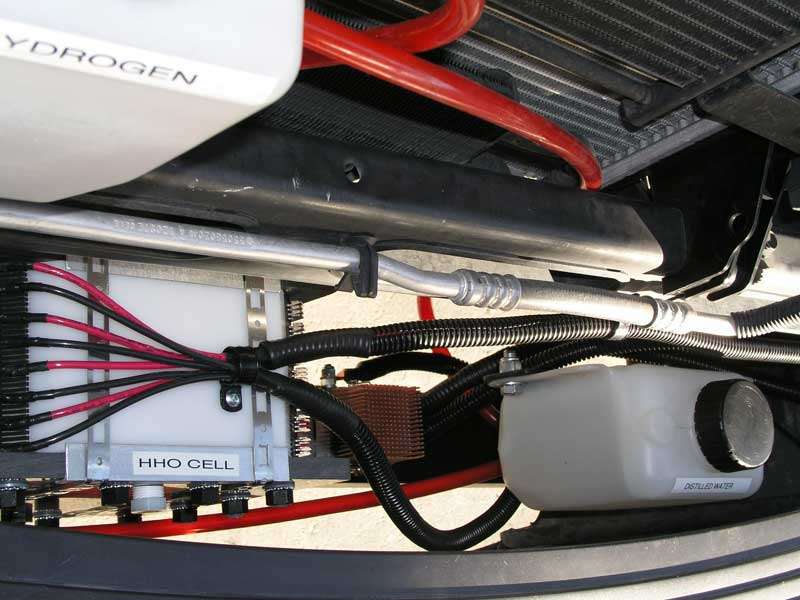
Well testing has begun. I made HHO gas today and here are a few videos of my results. I also tried my torch and it worked great. I could not see the flame but the torch worked and burnt the cardboard. I will do a video later tonight so that the readers can see the torch in action. The first video is production of HHO at 2lpm and the second video is production of HHO at 3lpm. Water temps in the reservoir at the bottom of the tank was 87 degrees while at the top I recorded 96 degrees. The cell felt warm as well.
In both test I had not made any adjustments to my PWM. I hope to make more HHO at lower amps.
Here is a reply from the builder of my PWM,
If you made gas at those 2 different currents, and you have not adjusted the CCPWM, I have to wonder where it is set at. You must 1st set the amps the cell will draw without the CCPWM, on 12Vdc, engine running & cold. Adjust electrolyte to the desired current.
Then connect the CCPWM and adjust it for the current you set the cell at with the electrolyte. Use a DC amps clamp meter at minimum. If you 40 amps on your cell, cold, w/out CCPWM, then you need to set the CCPWM to draw that 40 amps when connected. If the CCPWM is trying to regulate 40 amps and the cell is trying to draw say 60 amps, the CCPWM will do it for a while. The extra 20 amps in this example would have to go somewhere, and that is heat. If such condition exist, the CCPWM will burn up.
If the CCPWM is set at 40 amps and the cell draws 30 amps to start out, then the CCPWM will work fine and when the cell heats up to the 40 amps, the CCPWM will limit it to that 40 amps. But, in this situation, the cell would be likely to be overheating. It is important to match the cell draw closely to what the CCPWM is set for.
Ideally, if the cell is set to draw say 42 to 45 amps & the CCPWM is set at 40 amps, all is good for the balance of the 2. If the CCPWM is controlling the cell at 40 amps and the cell is no more than 45 amps, the CCPWM will keep it at 40 amps and the extra won't be very much over loading that would become wasted heat energy.
So the balance is important. If you have not adjusted the % Duty Cycle nor the Freq. yet, don't. Those can be played with later when you have equipment to measure frequency &/or see the signal on a scope. The pre set % Duty Cycle is at about 95% & the freq. is at 2.5KHz when I ship them out. You only need to get the current as close as you can to match the cell.
Hope this helps. Going to watch your videos now. Those are some very good numbers at those currents. If we spot anything in the video we will ask you about them.
Take care:
Rick Lawrence
Senior Member
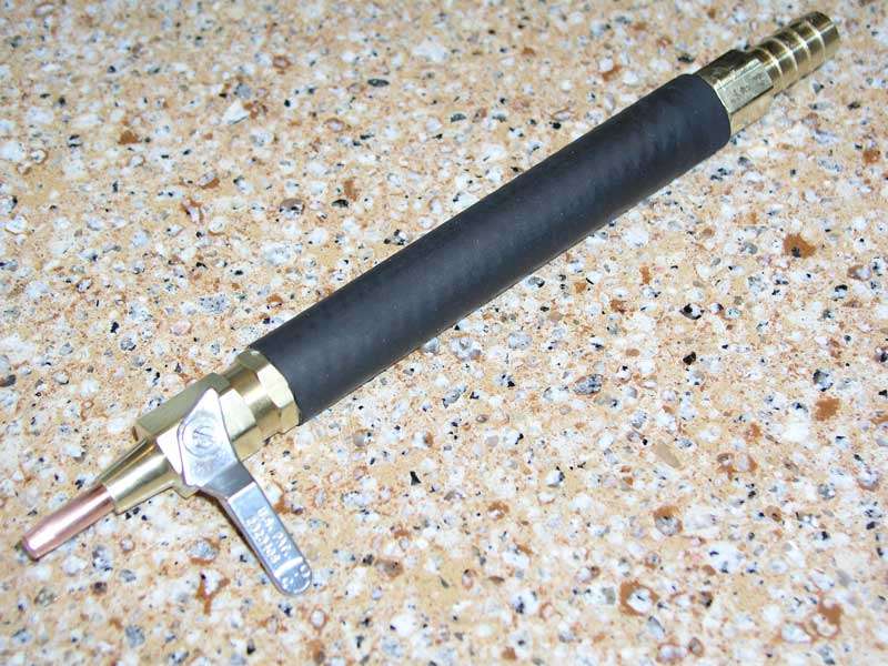
Here is my take on making a torch head. I used a 1/4" ball valve that is male NPT on one end and female NPT on the other end. The male end had the correct size center hole for a 1/4 x 20 tap. I tapped the hole of which a Hobart Mig Welding tips will screw into the male end of the ball valve. I believe this is a common thread size to mig welding tips so any brand will work.
Next I screwed the mig welding tip into the ball valve as tight as could and chucked up the tip in a drill. Using a file I removed the threads and tapped the brass on the male end of the ball valve.
I used a 6” x 1/4” brass pipe and Teflon tape both, next I threaded the pipe into the ball valve followed by a piece of neoprene hose for the handle, then bronze wool was placed inside of the pipe followed by the 3/8” hose barb on the other end.
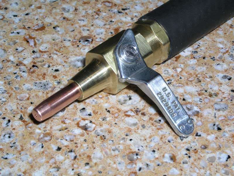
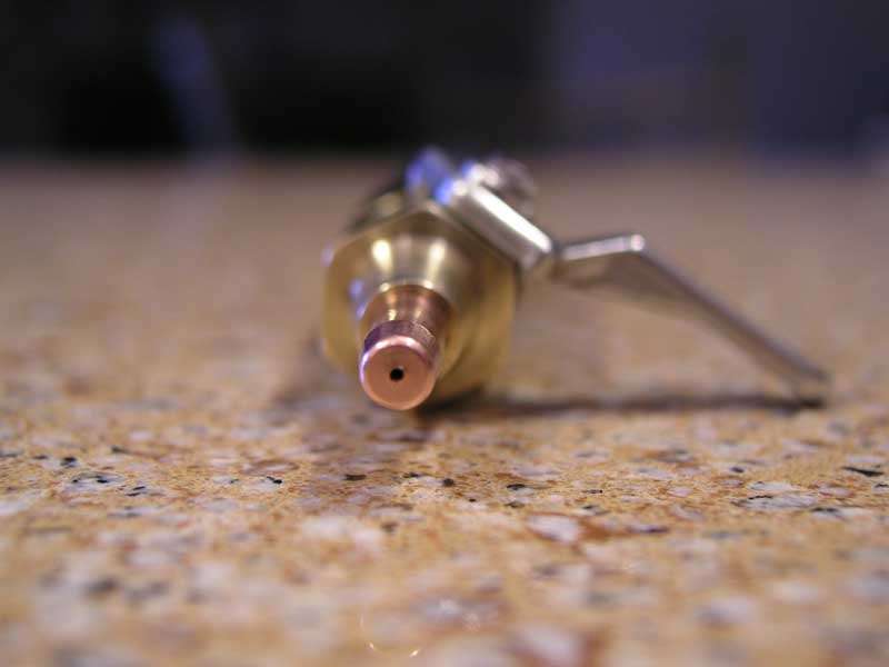
Mig Welding Tips are available from in many sizes. I currently have .023 and .035 tip sizes on hand. The shut-off valve will allow you to control the flow of gas as well. Pictured with the .023 tip
I can see how pressure would build inside the bubbler and cell block due to the small size tip… In my HHO design I have a thin piece of Saran Wrap as a pop-off on the fill caps of the bubblers.
As you can see this makes a very clean, simple torch for those that want to play.
Here is a quality HHO torch for your HHO projects Includes .035 screw in tip, this giving the user complete control of what size tip to use for the amount of litters of HHO gas being produced. Have complete control of the flame with the ball valve at your finger tips. Made of entirely of brass with the exception of the copper tip. The neoprene handle is 6 inches long with overall torch length of 10 inches. 3/8 barb hose fitting.

Senior Member
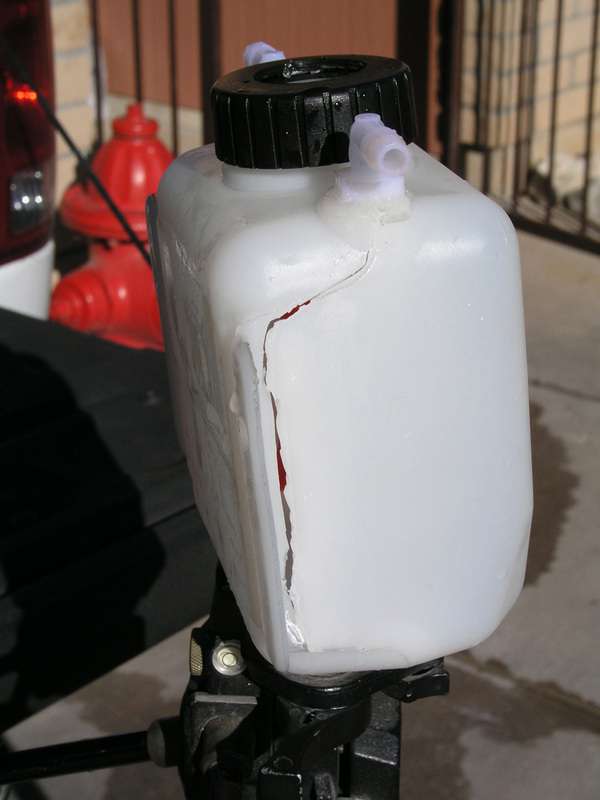
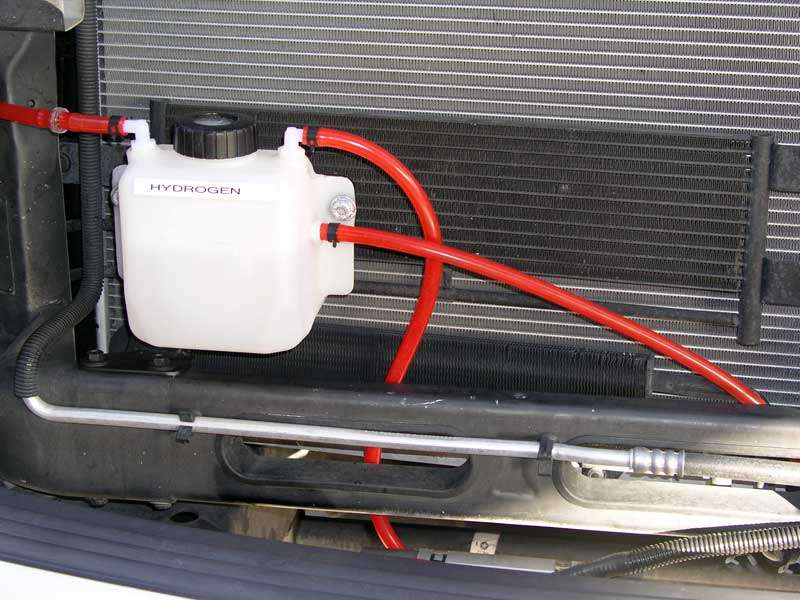
Well my bubbler did not last long… During my third demonstration of the torch to my neighbor I had a HUGE explosion. The first two demonstrations I had submerged the torch tip in a glass of water to shut the torch off as I was afraid to turn it off at the shut-off valve. But between the second and third demonstration I had lowered the electrolytes in the bubbler due to the foam, what I did not realized while lowering the level I was also increasing the amount of HHO gas in the bubbler. On the third attempt I submerged the torch tip in the water just as I had done before and BOOM!!! Not only did it blow the saran wrap plastic safety I had in the cap but the force of the explosion ripped the bubbler tank down the side as seen in these photos.
Super Moderator
Nice install, can't see all of the pictures seems some of the links are broken?
Russ.
Senior Member
Very nice looking set up and install. You spent some dough there. There is one thing I do not understand. That is your gaskets sticking to the plates. I have now switched to Nitrile but before had always used Neoprene. I probably tore down and rebuilt the cell dozens of times. The gaskets never stuck to the plates even a little. What grade, hardness, etc is the Neoprene. I could understand the sticking if you are using open cell Neo. The open cell's could create small vacuum cups that may stick in that way. If it is open cell Neo it will eventually become waterlogged and conductive causing issues.
Larry
Senior Member
Larry,Originally Posted by H2OPWR

The gaskets are hard neoprene. Beleive me even when the bolts are removed I would bet that the cells would stay together. When you wash the plates and gaskets in just water and pull them from the dishwasher and assemble the cells it a a freaken job to pull 36 plates apart. I am talking of hours to seperate the plates.
Russ,
I bet your trying to view the images at work where they block sites. I have the same problem and see many broken images from my work. The images are being served by FileDen...
Super Moderator
I'm using my blackberry at the moment which could be the issue, my home PC is down at the moment.
I will be at work in just over an hour and want to take a more detailed look at your posts then. I work in the I.T. department so blocked links won't be an issue :-)
Senior Member
BoyntonStu
 Posting Permissions

 Reply With Quote