Page 1 of 8 123 ... LastLast
Results 1 to 10 of 75

Thread: Anyone want to lower their cell temperature?

  1. #1
    Join Date
    Jun 2009
    Location
    Fort Worth, TX
    Posts
    510

    Anyone want to lower their cell temperature?

    I've got a good way... This really only applies to those cells that use a PWM to regulate the current through them. In addition, it applies to those cells that utilize a fairly low duty cycle(<90%)...

    The idea, is that when you are using a PWM, the instantaneous current through the cell is simply a function of the input voltage, divided by the cell resistance - a.k.a. Ohm's law = I = V/R. Nothing special here.

    However, POWER loss(heat) is a function of the integral of the current squared. If you are feeding your cell a square wave from a PWM at 50% duty cycle, then the AVERAGE current would be, say 30A, while the maximum current for nearly 50% of the time, would be about 60A peak. When comparing the power loss of a 50% duty cycle, 60A peak square wave, to a 30A smooth current, the power loss is:

    (R being the resistance of your cell)
    60A peak, 50% duty = 60^2*R*(50%) = 1800*R
    30A peak, 100% duty = 30^2*R*(100%) = 900*R

    In other words, if you are using a 50% square wave, your power loss is roughly TWICE as much as if you were using half the current, but a smooth signal.

    Since the amount of HHO is a function of how much charge passes through the cell(current * time), we can safely say that the two schemes listed above should produce about the same amount of HHO. Since we are making the same amount of HHO, and the power is reduced using the second method, we can also say that our MMW will be better as well!

    So, how do we smooth the current??? Pretty easily, it turns out. Using an power inductor and a single high current diode, we can manage to smooth the current to a pretty fair degree. However, there will be SOME additional power loss in the inductor and diode, but this should be minimal when compared to the gain by using this method.

    To understand what needs to be done, you may want to research what an inductor and/or a diode is. A diode essentially allows current to pass one way through it. An inductor resists changes in current, so if current is flowing through it, by god, that current will keep flowing through it(for a while...). Using the inductor, we can set up a fairly constant current, by means of a PWM. To do this, the PWM frequency will need to be set fairly high(frequency depending on the value of inductance used).

    The circuit is attached. More to come later, but I've got a date.
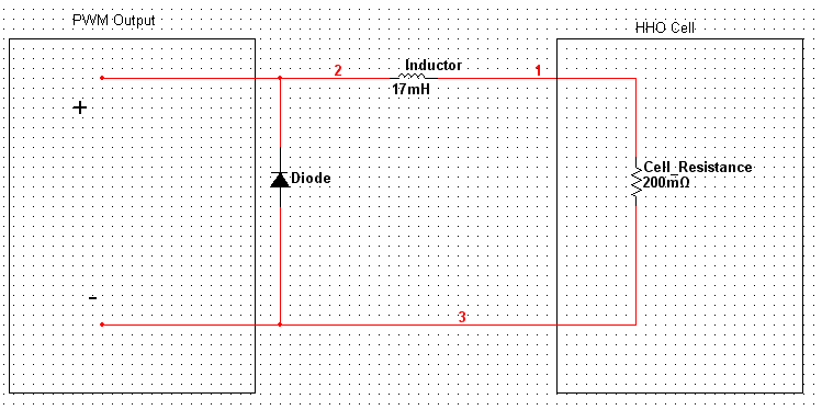
    Buck

  2. #2
    Join Date
    Aug 2009
    Location
    Dallas, TX
    Posts
    761

    whats his name?

    Ive seen Zero's PWM waves on his o-so-silly-scope and they are perfectly square. so if you monitor your PWM with the inductor & diode on a scope would they not be square? what would it look like?
    most of what you said is so far over my head its a spec in the sky. but I get the idea.
    The way I see it, if you're gonna build a time machine into a car, why not do it with some style?
    www.hhounderground.com

  3. #3
    Join Date
    Sep 2009
    Posts
    501

    Talking

    Quote Originally Posted by Philldpapill View Post
    I've got a good way... This really only applies to those cells that use a PWM to regulate the current through them. In addition, it applies to those cells that utilize a fairly low duty cycle(<90%)...

    The idea, is that when you are using a PWM, the instantaneous current through the cell is simply a function of the input voltage, divided by the cell resistance - a.k.a. Ohm's law = I = V/R. Nothing special here.

    However, POWER loss(heat) is a function of the integral of the current squared. If you are feeding your cell a square wave from a PWM at 50% duty cycle, then the AVERAGE current would be, say 30A, while the maximum current for nearly 50% of the time, would be about 60A peak. When comparing the power loss of a 50% duty cycle, 60A peak square wave, to a 30A smooth current, the power loss is:

    (R being the resistance of your cell)
    60A peak, 50% duty = 60^2*R*(50%) = 1800*R
    30A peak, 100% duty = 30^2*R*(100%) = 900*R

    In other words, if you are using a 50% square wave, your power loss is roughly TWICE as much as if you were using half the current, but a smooth signal.

    Since the amount of HHO is a function of how much charge passes through the cell(current * time), we can safely say that the two schemes listed above should produce about the same amount of HHO. Since we are making the same amount of HHO, and the power is reduced using the second method, we can also say that our MMW will be better as well!

    So, how do we smooth the current??? Pretty easily, it turns out. Using an power inductor and a single high current diode, we can manage to smooth the current to a pretty fair degree. However, there will be SOME additional power loss in the inductor and diode, but this should be minimal when compared to the gain by using this method.

    To understand what needs to be done, you may want to research what an inductor and/or a diode is. A diode essentially allows current to pass one way through it. An inductor resists changes in current, so if current is flowing through it, by god, that current will keep flowing through it(for a while...). Using the inductor, we can set up a fairly constant current, by means of a PWM. To do this, the PWM frequency will need to be set fairly high(frequency depending on the value of inductance used).

    The circuit is attached. More to come later, but I've got a date.

    Buck
    this is kinda backing my post that i made earlier when i said "the direction we will end up is high voltage and high frequency"

    good post phill

  4. #4
    Join Date
    Jun 2009
    Location
    Fort Worth, TX
    Posts
    510
    No, this has nothing to do with that post, Richard. Don't taint this thread with all that nonsense again...

    THIS has to do with providing a smooth, LOW voltage, current to the cell. The frequency is ONLY to sustain a stable current and NOTHING to do with the actual electrolysis.

    The point of this add-on, is so that the electrolyte ONLY sees the stable current. In fact, this sort of circuit is a type of LOW-pass filter, meaning only the low frequencies get through. The circuit results in less wasted heat from ohmic heating.

    You can contribute, but please, Richard, don't inject any magical "not-understood" garbage. The idea behind this is a basic power system concept in E.E.

  5. #5
    Join Date
    Aug 2009
    Location
    Dallas, TX
    Posts
    761
    Phill. are you building me a PWM? Im getting one with a "lot" of HHO suff Im buying but I really want the one you described to me earlier. just let me know what I owe ya or if you want some $ up front being that you live under the IH45 bridge and need the $.

    [will build PWM for food]
    The way I see it, if you're gonna build a time machine into a car, why not do it with some style?
    www.hhounderground.com

  6. #6
    Join Date
    Oct 2008
    Posts
    311
    Quote Originally Posted by Helz_McFugly View Post
    Phill. are you building me a PWM? Im getting one with a "lot" of HHO suff Im buying but I really want the one you described to me earlier. just let me know what I owe ya or if you want some $ up front being that you live under the IH45 bridge and need the $.

    [will build PWM for food]

    I gotta throw my 2 coppers in here because I think you guys are off base regarding a PWM's true function with an HHO system.

    Back in Jan. of 09 I refitted my large dry cell with 1/16" spacer gaskets from 1/8" and the amps went wild(as did my output).My heat wasn't out of control but after the cell warmed the amps like most cells rose to over 70 .After discussing this with one of the members here he suggested that I talk to Shane Jackson about him building me a custom high amp PWM with 2 built in mosfets,tested to over 100 amps.

    What the PWM did was keep my amps at an adjustable constant so my start up amps were the same as my warmed up amps thus giving me full control and being able to run the system at it's peak output even using a strong maximum e-lyte of 28% by weight KOH to distilled.I adjusted the amps so they were a constant 57 to 60 amps,which seemed to be the peak of performance for my cell and my charging system.

    So as they say here on the HHO forum sorry to disagree but...........

  7. #7
    Join Date
    Jun 2009
    Location
    Fort Worth, TX
    Posts
    510
    hg2, I must be a little stupid tonight... I don't understand where you disagree.

    The PWM design I'm talking about provides a CONTINUOUSLY smooth output current. The PWM shane jackson made(originally from zero fossil fuel) incorporates some feedback so that the current over a PERIOD remains constant. However, with his design, you will still have the current peaks, which result in unwanted power dissipation.

    With a true continuous current PWM, the average current and RMS current are the same. In other words, there are no high peak currents in the cell. This PWM design will also incorporate current feedback, so that it too is constantly adjusting the on/off times of the PWM.

    What do you disagree with?

  8. #8
    Join Date
    Aug 2009
    Location
    Dallas, TX
    Posts
    761
    when you would start it off cold at 57 to 60 amps what was your HHO output?
    and after it warmed up still drawing 57 to 60 amps what was the HHO output?
    How long did it take to warm up and how warm did it get at its peak with that KOH mixture?
    The way I see it, if you're gonna build a time machine into a car, why not do it with some style?
    www.hhounderground.com

  9. #9
    Join Date
    Jun 2009
    Location
    Fort Worth, TX
    Posts
    510
    @Helz,
    I've sourced some parts for the PWM units I'm building. I can't remember which type you wanted... 120VAC or 12VDC input? I've got way too many projects of similiar nature going on...

    As for the AC version, I think I've sourced some critical parts I needed. I'll try to get a prototype going next week. The cost is looking to be about $80 now... Things just keep adding up. What current rating did you want(assuming the 120VAC, up to 100VDC output)? I think you had said something about up to 75A... Remember, you can always use the higher output voltage to add more cells in series, then put the cells in parallel for a 12VDC use. Also, if you REALLY want 75A, at the 100VDC output voltage, that's 7.5kW of power, man! Yikes.

    Anyway, let me know what you want in this thing... I, too, have a shltty memory.

    @Richard,
    Please stop quoting long-a.ss posts by others. In this case, there was ONE other post before yours(Helz's). It's pretty clear who you were talking about, but by quoting everything anyone says, it makes the forum cluttered.

  10. #10
    Join Date
    Aug 2009
    Location
    Dallas, TX
    Posts
    761
    HA, no im not wanting a 100VDC/75 amps AC to DC. maybe a good ac to dc LATER, I have a good power supply for bench testing for now.. but yea one for a car. Digital LCD screen with Ampmeter and a volt meter on it. It would be nice to be ably to mod it with my laptop but thats not a demand. something that runs at peak 13.8VDC/150amps but Im sure I wont need more then 100 amps. I thought I had a 150 amp alternator on my car, because my brother said thats what he gave me, but I was told they dont make one for my car unless it was a custom build which it could have very well have been. Its probably a 160amp. I dont know untill I talk to his flakey a$$ tomorrow.

    Im pretty sure I wont be needing a PWM for 13.8VDC/100 amps in any of my cars. the largest enging I have is a 3.5 liter. V6.
    The way I see it, if you're gonna build a time machine into a car, why not do it with some style?
    www.hhounderground.com

Posting Permissions

  • You may not post new threads
  • You may not post replies
  • You may not post attachments
  • You may not edit your posts
  •