Looks like all but the last video have now been removed due to copyright claims. Shame the diagrams in that last video are not clearer.

 Super Moderator
Looks like all but the last video have now been removed due to copyright claims. Shame the diagrams in that last video are not clearer.
I'll be using 12vdc.Originally Posted by GOplayer

The resonate frequency of each generator is different. It should be between
20khz - 30khz. I don't understand why 99% of the PWM being sold only go up to 400hz.
The generator I am building produces very little heat, so current (Amps) is not one of my concerns.
I modified the design of the Dan Lawton PWM so that I have a higher frequency range.
I received the connectors for the PWM and completed the build up with the exception of the mosfet or amp (depending on what I want to use for the plate driver.)
I powered up the board and I had one small problem which was easy to correct.
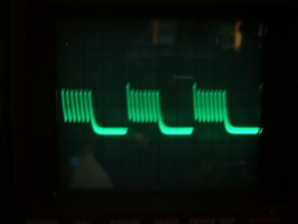
Here is a pic of the unadjusted output. When I feel like my brain is totally working i'll do some sdjusting on it.
As you can see it's running at about a 50% duty cycle.
The PWM by it's self draws about .05 amps @ 13.8V.
Junior Member
Glad to see the lawton circuits actually work for some ppl. I have tried all the different versions of Lawton's circuit, and am not impressed. I got nothing but a square wave generator and tiny bubbles. I also tried the 'Cramston' pll circuit, which is a joke. The only circuit I was able to get any results from was the Stan Meyer 8XA circuit I purchased online as a kit, http://www.stansdream.com/stan_8xa_board.htm . It puts out more HHO than any circuit I've tested to date. I am glad I stopped wasting my time with Lawton's bunk and found something that actually works. I'm glad to see it worked for someone though... Are you using any step-up or toroids on the output?
Junior Member
Just a couple questions. Great website!
I find it confusing because so many use brute force techniques and argue with efficiency studiers. They are part of the same big picture but employ different methods. I'm glad to see so much improvement in production in general over the years.
1. I see many people exclude the secondary part - induction coils - and/or info in this area is cloudy or MIA. Has anyone achieved the "pulse train of unipolar pulses" that effectually builds the voltage (thousands of volts) in the water capacitor?
2. Seeing this approach has alot to do with tuning, has any engineer or inventor constructed a cell that precisely follows the principles of capacitor production? ie. taking into account all factors related to the dielectric used (water) and specific working voltages desired. Probably has to be measured in cubits lol.
3. Has anyone injected the feedback of the pulse back into the circuit to make it "variable" or "self-harmonizing" as suggested by some websites?
I think because of the brute force scene, cell production technique is obscured. It only makes sense that the dimensions of the cell and materials would only apply to a specific electronic setup. There are constant themes revolving around resonance, frequency and escalating pulses suggesting the cell must promote harmonics.
I've accumulated lots of transistors, ics, coils, caps and transformers from old tvs. I am ready to build a driver but of course want to take the best EFFICIENT approach.
Junior Member
We at the University have taken Mr. Myers into great consideration into developing our On demand HHO System. He was a brilliant inventor, and will be remembered as the spark that started a new evolution to the free energy world.
we a experimenting right now with extremely high voltages and very low amperage within the electrolysis design to see if 10,000 volts with .005 amps (50 Watts) at the right frequency will give us more or the same output of hydrogen and oxygen. furthermore, we are separating the atoms, storing them up to about 45 PSI, and recombining them in the combustion chamber. This allows for safe compression, extraction of water mist, and a much more pure form of HHO to enter the combustion chamber.
Help is always welcome
Junior Member
Dewayne,
good point, i think most of the PWM's on the market are:
1. Fake
2. For something other then the cause of HHO
3. UN-educated individuals trying to make a buck.
4. all three of the above statements...
Junior Member
Great to see some people trying this out. We got Tony Woodside making kits available at globalkast.com, and irondmax at http://www.stanleymeyerwebshop.com/ selling boards. Aussies at thehydrodgenshop sells them. and hydrogenwaterfuel.com too. I don't to run the car on water, I just dont want to redesign the cars electrical system to get high enough conventional HHO output. I don't think I am getting enough HHO out of my mileage shop unit, about 1 lpm, running about 10 amps. It supposedly will make steam about 22 amps. I maybe got 1.5 lpm at +18. Couldn't get a good fuel usage calculation until I beat the +/- variation from fill-up to fill-up, and even corrected the 3% error on the odo. I notice the power increase, but overall I don't think I am getting enough production and I have been fooling myself watch a lucky drive in (no lights), getting maybe 32mpg on the scangauge. I think the ECU is cancelling out what benefit the HHO is giving. I have tried what mileageshop suggests, resetting the ECU and letting it learn with the HHO, nothing to write home about. Put a volo chip on, nothing much. Put a homemade wetcell in conjucntion, pretty sure got 2+ lpm, great power, mileage may have dropped! I am driving a 2002 Buick Century. Any way, Upping the output took +25amp and that alternator was much hotter than the top of the motor. So it just seems a better idea to find a way to get more HHO for less brute force amperage. But the biggest problem is the ECU. So you have to tune it. I am trying to build some Jaycar kits for the job. Of course they aren't off the test bench yet. See this article: http://www.free-energy-info.co.uk/D17.pdf. I don't feel like spending a thousand bucks to get everything put together and still not work, so its the slow way or no way. But assuming I get past the tuning, then its a higher output, lower amp circuit to build next. The Meyer kits not hearing that anyone has got them working yet, coil looks pretty tricky. Seeing some good vids on youtube on the Lawton circuit. Pretty sure it will get up to a few lpm under 5amps. The coil is much simpler. Also the neutral plate technology looks wrong on most dry cells for this type of circuit working by high voltage. needs +/- plate to plate pretty sure...
Junior Member
. Mike hho connections suggested I post on here.shorted Pwm cell is fine the electrolyte is ok suspect.bad Pwm.
Junior Member
I have a 19 plate dry cell and having problems with PWM. Shorting out code eo1 comming on sometimes or e03 don't know what to check next???
 Posting Permissions

 Reply With Quote