Page 2 of 3 FirstFirst 123 LastLast
Results 11 to 20 of 26

Thread: Help with plates

  1. #11
    Join Date
    Apr 2011
    Location
    Rimouski, Québec, CANADA
    Posts
    212
    Hi,

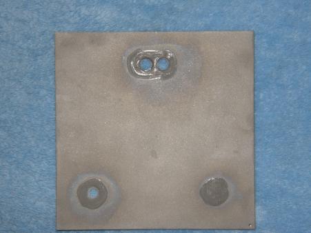
    Here is my 6" * 6" plates design

    Sand Blasted and holes insulate with IPS Weld-on 16

    One Input hole: 1/4"
    2 outpout hole: 5/16" (On my next generator, outpout hole will be 3/8/)

    EPDM Gasket 1/16" et HPDE Endplade
    2 stacks +NNNNN-F-NNNNN+ (F for full gasket)


    The reactor during cleaning process

    http://www.youtube.com/watch?v=LxMV9puZjys
    Civic Si 4 doors 2004, 1.7 liters V-TEC
    5N2 reactor
    CCPWM @ 7 amp
    1 Gal Capacity
    ~2% NaOH
    Waterless Peat Moss Bubbler

  2. #12
    Join Date
    May 2011
    Posts
    164
    Quote Originally Posted by j1walters View Post
    Havens, I see you have cut corners. I read that the hho production is less effective when corners are cut. Do you know if it makes a diffence? Also about porting I am wondering about the barbed fitting. Do you have two for gas and two for water (one on each side) or what seems to be the best route?
    I cut the corners of the neutral plates so that my power plates had square edges on them, I want to keep the connections close. And as far as the barbed fittings go i will have 1 inlet and 2 outlet for each stack. The stacks will be separated from each other so they are fed by the same reservoir but each side will have its own inlet and 2 outlets. This way I can test them separately if i need to or run them together while still monitoring the flow from each stack. I plan to drill from the top and sides for my inlet ports and outlet ports so that my fittings go in the side of the 3/4" and out the top. I'll get to these if I can this week and try to take a picture.

  3. #13
    Join Date
    May 2011
    Posts
    164
    Quote Originally Posted by j1walters View Post
    Myoldyourgold, I saw your post talking about magnetizing could you explain how to magnitize? I have looked but have been left clueless.
    I don't have the D9 on this computer or i would upload it. I magnetize my plates by stacking them in the order they will be assembled and wrapping them with 10 ga insulated solid copper wire about a dozen times. I leave about 10 inches on each end of the wire and 'tap' the bare ends of the wire on the positive and negative ends of a battery i have on the bench. I only do this 5 or 6 times as the wire gets hot very quickly and i'm not trying to make the plates a permanent electromagnet. Did i mention just to tap the wire? Okay, because you don't want it getting stuck trust me.

    I don't have scientific proof that it helps, only the experience that it seems to help gas flow. So this is purely my own experience and what I do as part of the conditioning process, so its up to you if you want to try it.

  4. #14
    Join Date
    Sep 2011
    Posts
    22

    Pics

    Yea do please send pics.

  5. #15
    Join Date
    Sep 2011
    Posts
    22

    gasket size

    Are you gaskets an inch or half an inch wide?

  6. #16
    Join Date
    May 2011
    Posts
    164
    Quote Originally Posted by j1walters View Post
    Are you gaskets an inch or half an inch wide?
    Those gaskets are 1/2" wide and 45 mil thickness.

  7. #17
    Join Date
    Sep 2011
    Posts
    22

    SO

    Are you suppose to keep the slot one inch from the top or does it not really matter with slots? I was reading myoldyourgold's set of guidelines.

  8. #18
    Join Date
    May 2011
    Posts
    164
    Quote Originally Posted by j1walters View Post
    Are you suppose to keep the slot one inch from the top or does it not really matter with slots? I was reading myoldyourgold's set of guidelines.
    When I did mine I wanted the top of the exit slots to be at the bottom of the gasket. I'll hopefully know how well it all works in the next week of so if I can actually get time in the garage.

  9. #19
    Join Date
    May 2011
    Posts
    164
    Quote Originally Posted by j1walters View Post
    Yea do please send pics.
    As requested here are the pictures of what i'm currently working on. The gas out is plumbed through the middle of the endplate and out next the slot in the plate. The markings are just for my reference and will disappear when i hit the endplate with acetone before assembly. Water in is plumbed through the side and out inside the plate opposite of the first plates' inlet hole.

    Still need to clean things up a bit and make sure things will flow correctly. Both endplates are done this way and the center plate is plumbed so that there are outlets for both sides of plates separated so I could run one stack of plates independently of the other if i needed to.

  10. #20
    Join Date
    Sep 2011
    Posts
    22
    What's the reason for the barbs on the endplates like you have instead of putting them on the sides?

Posting Permissions

  • You may not post new threads
  • You may not post replies
  • You may not post attachments
  • You may not edit your posts
  •